Reslice
At a glance
- What the view shows: cut a fresh slice stack along this exact structure, a straight line at any angle or a curved arc, where the fixed planes do not reach.
- Start: scroll the scout to the slice where the structure is best defined, draw the path (drag a stroke, or click points: two make a line, three or more an arc), double-click to finish, then choose the Cross or Parallel output shape.
- Three gestures: on the scout, drag or click draws the path and the wheel scrolls; right-drag on an output tile tilts the stack. The Keys card lists every gesture of the mode.
- Leave it for: measurements, which live in MPR; the dental arch (Pano) and the condyles (TMJ) have their own, specialized versions of this mode.
What this mode is for
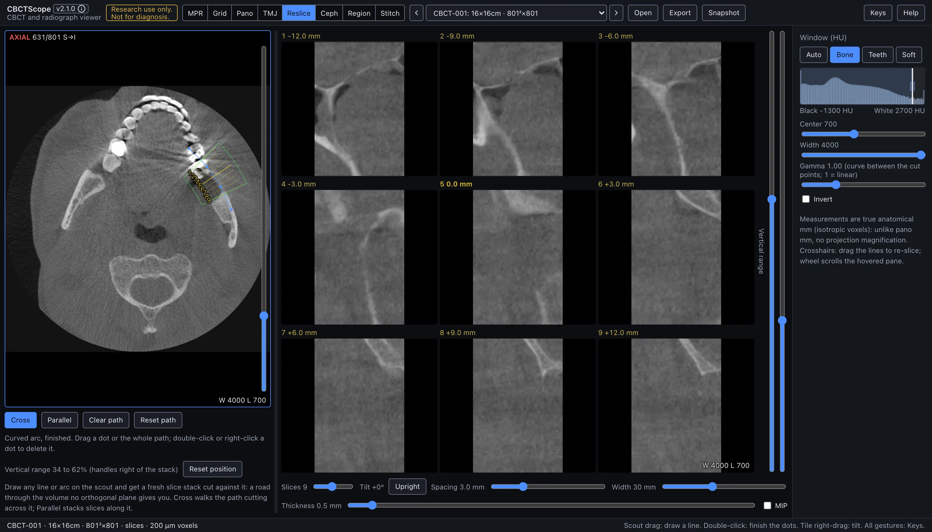
Reslice generates a fresh 2D slice stack along any path you draw on the axial scout: a straight line at any angle, or a curved arc. It answers the question the fixed planes cannot: "cut me a stack of slices along this exact structure," whether that is serial cross-sections marching down a drawn line or a stack of parallel reformats through a chosen direction. It is the general-purpose version of what Pano does for the dental arch and TMJ does for the condyles.
Gestures
| Gesture | Where | Action |
|---|---|---|
| Drag a stroke, or click points | scout, while placing | Draw the path: two points make a straight line, three or more make a curved arc |
| Double-click | scout, while placing | Finish the path |
| Drag a dot | scout, once finished | Refine the path |
| Drag the line | scout, once finished | Move the whole path |
| Right-click a dot | scout, once finished | Delete it |
| Wheel | scout | Scroll the slice; the caption uses the MPR axial count (S→I, slice 1 at the top) |
| Right-drag | any output tile | Rotate the stack (tilt) |
| Drag the divider | between scout and stack | Resize; double-click resets |
| Double-click a crop handle | stack edge | Reset it |
The path has the same two-phase lifecycle as the pano arch: while placing, strokes and clicks add to it; once finished, clicks are inert and only the dots and the line respond. The path and the scout slice persist per volume.
The controls
| Control | Options or range | What it does |
|---|---|---|
| Panes | scout, stack | The scout shows AXIAL n/N top left and the window bottom right; each slice's number and offset sit in a strip above it, and the window is bottom right of the last slice. The pane that takes the wheel carries a thin blue frame, and the axial level is the reading place shared with the other modes (section 3.3). |
| Clear path | button | Removes the whole path and returns to placing. |
| Reset path | button | Returns the path to its position as of the last finish. |
| Output shape | Cross | Planes perpendicular to the path, marched along it. On a line this walks the line cutting across it; on a curve it steps along the arc cutting perpendicular cross-sections, as in the Pano cross-sections. |
| Parallel | Planes containing the path direction, offset sideways. On a line this is a stack of parallel oblique reformats; on a curve it is the arc swept at a series of sideways shifts, a stack of curved reformats. The selected shape is solid blue. | |
| Slices | 3 to 16 | How many slices the stack holds. |
| Tilt, Upright | readout, button | The stack's tilt in degrees, and the button that sets it back to 0°. |
| Spacing | 0.5 to 10 mm | The distance between slices. |
| Width | 10 to 60 mm | The width of each slice. |
| Thickness | 0 to 10 mm | Averaged into each slice. |
| MIP | checkbox | Brightest voxel instead of the average, for straight-line stacks and parallel curved reformats. |
| Vertical range | two handles on the right edge of the stack | Trim its top and bottom; the kept band scales into the pane, and double-click on a handle resets it. |
| Stack rotation | right-drag on any output tile | The same sweep gesture as the MPR and grid rotations. The frame is rigid: the scout goes oblique to match and the drawn path projects onto it dashed while tilted. |
| Reset position | button | Returns the tilt upright and the vertical crop to full, leaving the path, stack parameters, and the divider untouched. |
| Snapshot | header button | In this mode it saves the whole stack as one PNG, tiled, with a caption line carrying the volume id, stack geometry, and date. |
| Scout markers and tiles | scout, tiles | The scout draws the path plus numbered markers showing where each output slice cuts, and outlines the sampled band in green, showing exactly the anatomy the stack cuts through; the output tiles carry the matching number and the offset in mm from the path midpoint. The middle slice of the stack is highlighted on both sides. |
| Window | shared sidebar | The shared Window (HU) presets, center, width, and invert apply. |
A reading workflow
- Scroll the scout to the slice where the structure of interest is best defined and draw the path along it: a line for a straight course, an arc for a curved one.
- Choose the output shape from the question: cross-sections to examine a structure's short axis repeatedly along its length, parallel to view it in its own long-axis plane at several depths.
- Set Spacing so the stack spans the structure with the sampling you need; the slice count times the spacing is the total coverage, centered on the path midpoint.
- Set Width generously at first, then tighten it once the stack is centered where it should be.
- Keep Thickness near zero for fine detail, and add thickness or MIP when continuity through noise matters more than edge sharpness.
- Use the numbered markers on the scout to keep every output tile anchored to its position in the anatomy.
- Trim the vertical range to the region of interest so each slice is filled with relevant anatomy.
- Save the stack as a PNG when the series itself is the record, or reproduce the key position in MPR for measurements.
Over MCP
open_scan, list_volumes, select_volume, set_view_mode (mode reslice),
set_window_level, and snapshot apply; the snapshot captures the scout and the output
stack as laid out. navigate_slice has nothing to move here (it works in MPR, grid, and pano) and answers with a clear error; the path is drawn by hand and has no
agent verb. Example sequence: set_view_mode to reslice, set_window_level preset
Bone, snapshot.
Limits
The stack exists only after a path is drawn, and its geometry is exactly the drawn geometry: there is no automatic alignment to anatomy. The path is drawn on one axial slice, so the cutting frame is defined in that plane; structures whose course changes out-of-plane may need the path redrawn at another level. There are no measurement tools here; measure in MPR. CBCTScope is navigation and visualization only: no findings, no diagnoses. Research use only; not a medical device.